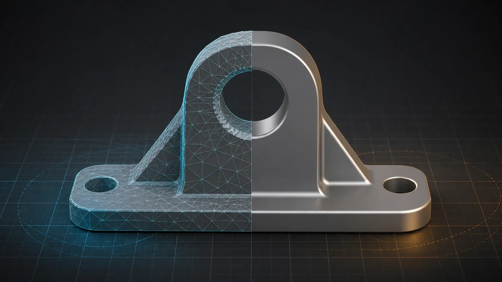
Yes, you can convert an STL file to STEP. The resulting file may open successfully in CAD software and may even be reported as a solid body. However, conversion alone does not restore the sketches, dimensions, holes, fillets, constraints, or feature history that existed before the model became an STL.
That distinction explains the most common surprise after an STL-to-STEP conversion: the operation succeeds, but changing a 20 mm hole to 22 mm is still difficult. The file format has changed. The underlying geometry may still be a collection of triangles.
This article explains what the converted STEP contains, how to tell whether it is faceted, which editing methods are realistic, and when the result is suitable for CNC machining.
A STEP File Is Not Necessarily a Parametric CAD Model
STEP is a product-data exchange format. It can represent precise curves, analytic surfaces, solids, assemblies, and other engineering data. That capability sometimes creates the impression that every STEP file must contain clean, editable CAD features.
It does not.
A STEP file can describe a cylinder as a true cylindrical surface. It can also describe a similar-looking shape as hundreds of small planar faces. Both files may be structurally valid STEP files, but they behave very differently in a CAD system.
It helps to separate four levels of success:
| What you observe | What it actually proves |
|---|---|
The converter produces a .step or .stp file | The format conversion completed |
| CAD software opens the file | The file structure and geometry are readable |
| CAD software reports a solid body | The faces form a closed volume the application can treat as a solid |
| Hole sizes, fillets, sketches, and extrusions are editable | Features were preserved, recognized, or rebuilt |
Many automatic STL-to-STEP conversions reach the first two levels. A clean, watertight mesh may reach the third. The fourth usually requires feature recognition or reverse engineering rather than format conversion.
The Information Was Lost When the Model Became STL
Suppose the original CAD model had a circular hole with a diameter of 20 mm. In the native design, that hole may have been created by a constrained sketch followed by an extrude-cut operation. The CAD system knows that the geometry is a hole, knows its diameter, and knows how it relates to the surrounding part.
STL stores none of that design logic. It stores the final surface as triangles. The circular wall becomes a ring of flat facets. A dense mesh can look smooth on screen, but its triangles do not know that they once approximated a cylinder.
The same loss applies to:
- sketch dimensions and geometric constraints;
- extrusion, revolve, loft, and sweep operations;
- hole definitions and thread metadata;
- fillet and chamfer features;
- assembly relationships;
- the order of operations in the feature tree.
Converting the STL back to STEP is similar to placing an image of a spreadsheet into spreadsheet software. The visible result is present, but the formulas that produced it are not.
What FabRapid Creates When Converting STL to STEP
FabRapid's current STEP exporter writes an ISO 10303-21 file using the AP214 AUTOMOTIVE_DESIGN schema. Mesh geometry is stored as FACETED_BREP: each non-degenerate source triangle becomes a planar STEP face bounded by a polygon loop.
The result has a standard STEP container and can enter software or workflows that accept STEP but not STL. It does not infer the original sketches, dimensions, extrusions, holes, chamfers, or fillets. It also does not recreate the original feature tree.
This is why the STL-to-STEP tool warns that the output is tessellated geometry in a STEP container, not editable CAD features. The warning describes the geometry, not a failed conversion.
The difference is also visible in the file entities. A faceted result contains entities such as FACETED_BREP, many planar ADVANCED_FACE records, and polygon loops. A STEP model built from analytic CAD geometry may contain cylindrical, conical, spherical, or spline surface definitions instead. CAD applications do not always expose those entity names in their interface, but an importer or diagnostic tool can inspect them.
FabRapid currently gives a proactive route-level warning for mesh-to-CAD conversions. It does not claim to reconstruct features or dynamically certify that an arbitrary uploaded STEP file is parametric. You can use the STEP viewer to inspect the visible model, but visual smoothness alone is not proof of analytic surfaces or editable design history.
What Can You Still Edit?
A faceted STEP is not useless. The realistic editing options depend on the model, the number and quality of its triangles, and the tools available in your CAD system.
1. Direct mesh or faceted-body edits
You may be able to move, scale, cut, combine, or delete portions of the model. Some CAD systems support Boolean operations between mesh B-Rep and standard solid geometry. This can be enough for a fixture, a clearance cut, a simple mounting addition, or a rough visual modification.
The limitation is local intent. Selecting what looks like one cylindrical wall may actually select dozens or hundreds of faces. A direct modeling command that works naturally on one analytic cylinder can become slow or impractical on a faceted approximation.
2. Convert or recognize simple geometry
Some CAD applications can group triangles and recognize planes, cylinders, cones, or spheres. Autodesk Fusion, for example, offers faceted and prismatic mesh conversion methods. Its Convert Mesh documentation explains that faceted conversion retains individual mesh faces, while prismatic conversion can merge face groups into singular faces inferred from prismatic features.
SOLIDWORKS also documents a Mesh to Standard BREP workflow for segmented meshes with recognized planar, cylindrical, conical, or spherical geometry.
These tools can be effective for clean mechanical parts. They are less predictable on noisy scans, organic forms, damaged meshes, or models with dense and irregular tessellation. Recognition is an interpretation of the mesh; it is not recovery of the original design history.
3. Reverse-engineer the part from mesh sections
When dimensions matter, rebuilding is often more reliable than trying to edit every triangle. Use the STL or faceted STEP as a reference, create section planes, fit lines and arcs to those sections, add measured constraints, and reconstruct the part with normal CAD features.
Autodesk's mesh section sketch workflow is one example. It allows lines, arcs, circles, ellipses, and splines to be fitted to a mesh section, after which the profiles can be used to recreate parametric solid or surface bodies. The fitted curves still require engineering judgment, tolerances, and often manual constraints.
For a simple bracket, flange, enclosure, or turned component, this approach may be faster than repairing a large faceted B-Rep. For a complex freeform scan, specialist reverse-engineering or surface-fitting software may be more appropriate.
4. Obtain the original CAD file
If accurate edits are required, the best option remains the original native CAD file or a precise exchange file exported before tessellation. Useful sources include a native part file, STEP with analytic surfaces, IGES, Parasolid, or another format that preserves the required geometry.
Start with the original whenever you need controlled hole sizes, wall thicknesses, mating faces, tolerances, or design revisions. Reverse engineering should be the fallback, not the default, when an authoritative model still exists.
Is an STL-Derived STEP Suitable for CNC Machining?
Usually, it is not the preferred master model for precision CNC work.
A CAM system may accept the file because it is STEP, and some CAM systems can generate toolpaths from meshes or faceted bodies. Compatibility does not make the geometry precise. The converted surface still follows the vertices of the source STL, so its accuracy is limited by the original tessellation, units, mesh quality, and any defects in the source.
Curves are the main concern. A true cylindrical bore gives CAM software an analytic surface. An STL-derived bore is a polygonal approximation. Depending on the CAM strategy, tolerance settings, and mesh density, the toolpath may follow those facets, approximate them again, or reject the body. Dense meshes can also make selection and toolpath calculation unnecessarily heavy.
Use this decision guide:
| CNC task | Is a faceted STEP appropriate? | Recommended action |
|---|---|---|
| Visual reference, quoting, or fixture planning | Often acceptable | Verify scale and overall dimensions |
| Roughing a non-critical or organic shape | Possibly | Confirm the CAM system supports faceted geometry and simulate the toolpath |
| Adding a simple cut to a low-risk part | Possibly | Rebuild or recognize the critical faces first |
| Finishing precision bores, sealing faces, or tight-tolerance features | Usually no | Use the original CAD model or reconstruct analytic surfaces |
| Production release or inspection master | No, unless formally validated | Use controlled engineering geometry and the required drawing or PMI |
Before machining from any STL-derived model, verify at least the following:
- Units and scale: STL has no dependable built-in unit declaration. Confirm a known dimension before generating a toolpath.
- Mesh closure and defects: Check for holes, self-intersections, non-manifold edges, duplicated faces, and degenerate triangles.
- Facet deviation: Determine whether the original STL resolution is finer than the manufacturing tolerance required on every critical surface.
- Recognized critical geometry: Rebuild bores, datums, sealing faces, and mating features as analytic CAD surfaces where possible.
- CAM behavior: Confirm the selected CAM system's documented support, toolpath tolerance, and handling of faceted bodies.
- Simulation and inspection: Simulate the complete toolpath and inspect the machined result against the authoritative dimensions.
Changing the extension from STL to STEP should never be treated as manufacturing validation.
Which Workflow Should You Choose?
The right path depends on the result you need, not the file extension you prefer.
| Your actual goal | Best starting point |
|---|---|
| A downstream system accepts STEP but rejects STL | Convert the file and use the faceted STEP as a compatibility handoff |
| View, measure, or place the model in an assembly as a reference | Convert or open the mesh, then verify units and orientation |
| Make one coarse cut or Boolean change | Try direct mesh or faceted-body tools |
| Change mechanical dimensions accurately | Use feature recognition or rebuild the affected geometry |
| Recover sketches and the original feature tree | Obtain the native CAD file; automatic format conversion cannot recover it |
| Prepare a precision CNC master | Use analytic CAD geometry or a validated reverse-engineered model |
If your immediate need is compatibility, you can convert STL to STEP in the browser. If you are deciding which representation should be kept as the source of truth, compare the STL format with the STEP format and keep the most information-rich original available. Our guide to 3D printing file formats also explains why STL and STEP serve different stages of a manufacturing workflow.
The Practical Answer
An STL-to-STEP conversion can create a valid and useful STEP file. It can solve an input-format restriction, make the model easier to exchange with CAD-oriented software, and enable some solid or direct-modeling operations.
It cannot recreate information that STL no longer contains. If the converted part is covered in triangular faces and lacks sketches or features, the conversion has not failed. It has preserved mesh geometry inside a STEP representation.
For limited edits, try mesh cleanup, face grouping, prismatic recognition, or direct modeling. For dimensional changes and CNC-critical surfaces, use the mesh as a reference and rebuild the required geometry, or return to the original CAD source.
- Author: FabRapid Engineering
- Technical review: FabRapid conversion engine maintainers
- Published and last reviewed: August 18, 2026
Technical basis: FabRapid product behavior in this article was verified against the current STEP exporter implementation on August 18, 2026. CAD editing examples link to the relevant Autodesk and SOLIDWORKS documentation. Manufacturing decisions should still be validated against your CAM system, tolerance requirements, and inspection plan.